Device updates bring new features, improve system stability and enhance performance. It is therefore important to regularly check the status of all Duplex system components and keep them up to date. Updates are provided free of charge by JETI model, including the JETI Studio software.
JETI Studio
JETI Studio is an advanced software tool for the Duplex system, available for free download from the manufacturer’s website. Select the correct version for your computer and install the program.
Main functions of the software include:
• Updating Duplex DC/DS transmitters
• Backing up transmitter data, models, and configuration
• Updating receivers, speed controllers, and other Duplex devices
• Graphical display of telemetry logs from the transmitter, analysis of measured values, and event reconstruction
• Real-time telemetry monitoring during flight
• Configuration of devices that support the EX Bus protocol
Transmitter Update and Data Backup
• Open the JETI Studio program and connect your transmitter to the PC using the supplied USB cable
• On the transmitter, press the F5 button under the screen to confirm “Connect to PC”
• In the JETI Studio menu, go to Tools > Transmitter Wizard and launch the Transmitter Update wizard, then follow the step-by-step instructions
• After the process completes, disconnect the transmitter from the PC, turn it off, and then back on to allow the installation of the new files

Tip: During the update process, you can initiate a backup of your transmitter data. The complete transmitter settings and stored models will be saved in JETI Studio. This allows you to revert the transmitter to a previous state as of the backup date. Since model configurations are included in the backup, it’s recommended to perform a backup after setting up and fine-tuning each new model.
Updating Receivers and Telemetry Sensors
To update Duplex system receivers and telemetry sensors, you need the JETI Studio program installed and the USB Adapter device. The USB Adapter connects devices to the computer’s USB port.

• Launch the JETI Studio program and go to Tools > Device Update
• Plug the USB Adapter into a free USB port on your computer (a green LED will light up on the adapter)
• Select the correct COM port from the list. Successful selection is indicated by a blinking red LED on the USB Adapter (signaling communication)

• Connect the USB Adapter to the Ext. port of the device you wish to update
• The connected device type and firmware version will appear in the upper window of JETI Studio
• In the lower right window, all available firmware versions will be listed. Select the appropriate version (usually the latest) and click Update to begin

Note: In the lower right window, a changelog describes what’s new or changed in the selected firmware version compared to the previous one.
Updating MEZON EVO and Newer ESCs
Warning: ESCs from the Spin, Advance, and JES series do not support firmware updates.
Warning: During the update, do not connect the black connector cable from the ESC to any device.
• Start the JETI Studio program and go to Tools > Device Updater
• Plug the USB Adapter into an available USB port on your PC (a green LED will light up)
• Select the correct COM port from the list. The correct choice is indicated by a blinking red LED on the USB Adapter (communication in progress)
• Connect the three-wire cable with red JR connector from the ESC to the USB Adapter
• For OPTO-type ESCs and all MEZON EVO / MEZON PRO controllers, connect a main power supply battery (For ESCs with BEC/SBEC, turn on their switch)
• The connected ESC and its current firmware version will appear in the upper window of JETI Studio
• In the lower right window, all available firmware versions for the device will be listed. Choose the appropriate version (usually the newest one) and click Update to begin

Updating Central Boxes
Update Central Boxes using the same procedure as OPTO-type ESCs. This means that after connecting the Central Box to the USB Adapter, you must also supply power to at least one of the main BATT inputs on the Central Box.
JETI Studio
JETI Studio is a free PC software for viewing telemetry data, updating, and configuring Duplex system devices. It is available for download at www.jetimodel.cz.
Main features of the program:
- Display of telemetry flight logs from the transmitter memory
- Backup and restore of transmitter configuration (see next page)
- Firmware updates for transmitters, receivers, ESCs, and telemetry sensors (see next page)
The ability to display telemetry data logs helps fine-tune model settings and verify correct installation of components. All Duplex system receivers provide basic telemetry data, such as signal strength on each antenna, signal quality, and receiver voltage. Additional telemetry depends on the sensors installed in the model.
Viewing telemetry logs in JETI Studio
- Install and run JETI Studio on your PC
- Connect your transmitter to the PC using a USB cable, turn it on, and confirm USB connection
- From the transmitter’s “Log” directory, select the desired model and specific flight. Logs are organized by “date/model name/flight time”
- Use “Menu / Add window” to create the number of display windows needed and choose how the data will be presented (graph, numeric, etc.)
- Drag and drop telemetry values from “Available telemetry” into each created window

Tip: You can display multiple values in a single window. For example, one graph can show current, ESC temperature, and battery voltage simultaneously.
Example of Displaying Selected Data

- Display of available telemetry, connected sensors, and list of data that can be shown for the selected model
- Flight time selector cursor
- Playback controls – play, pause, and speed of replay for the selected flight
- Graph showing signal quality (red) and signal strength on both receiver antennas (green and yellow)
- Signal strength A1/A2: numerical values representing the strength of the signal received on each antenna of the receiver. These are approximate values that decrease non-linearly with distance.
- Signal quality Q: indicates the success rate of bidirectional communication between the transmitter and receiver in percentage. The return signal from the receiver is always weaker than the transmitted signal from the transmitter. This means that even with a signal quality of “0”, the model remains controllable, only the telemetry data from the receiver is not received.
- Numeric values measured by the ESC (current draw, battery voltage, consumed capacity, ESC temperature). Minimum and maximum values during the flight are shown on the right.
- Display of current G-force
- Artificial horizon showing model orientation in space
- Complete flight path with current model position overlaid on a real-world map background. JETI Studio allows you to choose from various map types provided by Google or Microsoft. The flight path is color-coded to represent the model’s altitude.
Basic settings for ASSIST receivers.
Receiver Preparation
- Using a USB adapter, PC, and the JETI Studio software, verify that your receiver is running the latest firmware version.
- If the receiver has been previously used in another model, perform a format via the transmitter in the menu Menu/Applications/Jetibox while the paired receiver is powered on.

- Bind the receiver to the transmitter.
- Set up the model functions as you would with a standard receiver.
- Install the receiver in the model on a flexible mounting pad to secure it against movement (ideally, use the supplied double-sided foam tape). Position the receiver as close as possible to the model's center of gravity, aligned with the longitudinal, lateral, and vertical axes of the model.
Transmitter Preparation
- Connect the transmitter to your PC using a USB cable and verify that it is running the latest firmware version using the JETI Studio software. The minimum required version is v4.24.
- In the transmitter menu Menu/Model/Function Assignment, create a new function that will be used to switch stabilization flight modes (e.g., Mode), and another function to control its sensitivity (e.g., Gain). Assign controls to these functions — a three-position switch is recommended for the Mode function, and a rotary knob for Sensitivity (Gain).

- In the transmitter menu Menu/Model/Servo Assignment, assign these new functions to unused channels that are not required for other controls.

Basic Assist Setup
Perform the basic setup using the setup wizard launched from the transmitter in the receiver menu:
Menu/Model/Device Explorer/Receiver Type/Configuration/Quick Wizard. Carefully follow the steps one by one.
- When selecting “All servos digital”, the output period for all servo outputs will be set to 7.5 ms. Otherwise, it will be 17.5 ms. Make sure that all devices connected to the receiver support the selected output period.
- Perform the calibration of the controls very carefully and according to the instructions in the “Primary Channel Assignment” menu.
- For the “Flight Mode Channel”, assign the flight mode switch that was configured in the “Transmitter Preparation” section (the Mode switch).
Gain Control Setup (Stabilization Sensitivity)
To the “Gain Tuning Channels” option in the receiver menu under Configuration > Channel Assignment > Assign additional channels, assign the control (Sensitivity / „Gain“) set up earlier in the “Transmitter Preparation” section.
You can assign a single control for adjusting the gain of ailerons, elevator, and rudder together, or use separate controls for each surface.

Note: The percentage value shown in the “Gain Tuning Channels” menu reflects how much higher or lower the final gain is compared to the base gain value configured in the receiver menu Configuration > Airplane Settings.
Stabilization Mode Setup
The Assist system offers six predefined stabilization modes, out of which you can select three to switch between during flight. Mode switching is controlled by the switch assigned earlier in the “Transmitter Setup” section. Each selected mode can be fine-tuned via the “Edit” option in the menu.


Description of Available Modes:
- Manual (Assist Off) – Stabilization is disabled.
- Training – Dampens wind gusts and limits maximum bank angles on all axes. The angle limits are adjustable. Ideal for learning to fly; aerobatics are not possible in this mode.
- Horizon – Automatically returns the model to level flight from any attitude. Recommended for temporary use in emergencies. Each time the control stick returns to neutral, the model is actively leveled.
- Normal (Damping) – Basic stabilization mode. Smooths out flight and reduces effects of wind and turbulence without restricting control sensitivity or aerobatics.
- Heading Hold (Lock) – Stabilization actively holds the model’s current position. Ideal for hovering, low passes, and knife-edge flight. Not recommended for takeoff or landing.
- 2D Mode – Similar to “Trainer” but adds active altitude stabilization. If the elevator control is not touched, the model maintains altitude within 1–2 meters.
First Flight with Assist
- After trimming and fine-tuning your model, perform Assist stick calibration.
- In Horizon mode, with high gain set, verify the direction of stabilization responses—control surfaces should move opposite to the direction you tilt the model.
- Before takeoff, set the stabilization gain control to minimum and switch to Manual mode (stabilization off).
- Once in steady level flight, switch to Normal mode. Fly calmly with gentle bank angles. Gradually increase stabilization gain until the model starts to feel twitchy or overreactive (over-stabilized). Slightly reduce the gain to ensure the model remains stable, even at higher speeds.
- For fine-tuning, you can adjust gain sensitivity per control surface (see section “Stabilization Gain Control Setup”).
For Proper Operation of the Stabilization System, Please Follow These Recommendations
- Regularly update the transmitter and receiver firmware.
- After each model trimming, recalibrate the Assist system (see chapter “Basic Assist Setup”).
- Recalibrate Assist every time you replace a servo in the model.
- Upon powering on, keep the model still and level until the system announces it's ready for flight.
- Assign Manual mode to the first position of the flight mode switch to allow quick deactivation of stabilization at any time.
- Ensure the onboard power supply is sufficiently dimensioned—models with active stabilization have increased power consumption.
- If in doubt, contact JETI model technical support or your local dealer for assistance.
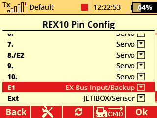
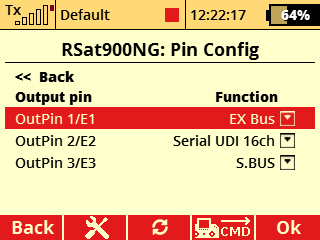
Examples of Selected REX Assist Receiver Configurations
a) Configuration with a REX10 Assist receiver and an Rsat900NG satellite receiver for the 900 MHz band.
- E1 serves as the EX Bus input/backup.

b) Configuration with a Central Box, REX9 Slim Assist receiver, and Rsat900NG satellite for the 900 MHz band.
- Even in the event of a 2.4 GHz signal loss and switch to 900 MHz, the stabilization remains fully functional.
- Fail-Safe is disabled on both receivers (including “intelligent” mode), but enabled in the Central Box.

c) Similar setup using two 2.4 GHz receivers.
- In the transmitter menu under Advanced Properties → Wireless Modes/Trainer, set the mode to Double Path.
- Fail-Safe is disabled on all receivers (including “intelligent” mode), and enabled in the Central Box.

Bind both receivers with the DC/DS transmitter in the Double Path mode (or set the backup receiver to CLONE mode).
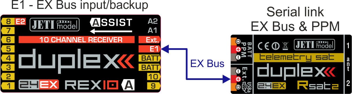

Connecting the main receiver and Rsat 900 NG backup

Update procedure JETI EX receivers (Rx and REX) by JETI Studio.
All receiver updates are performed automatically by JETI Studio. All users have a very fast and easy way to update their receiver to the latest version of FW with all the new features.
The complete procedure is shown in the video below.
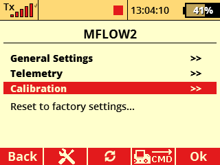
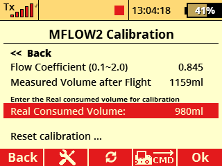
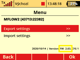
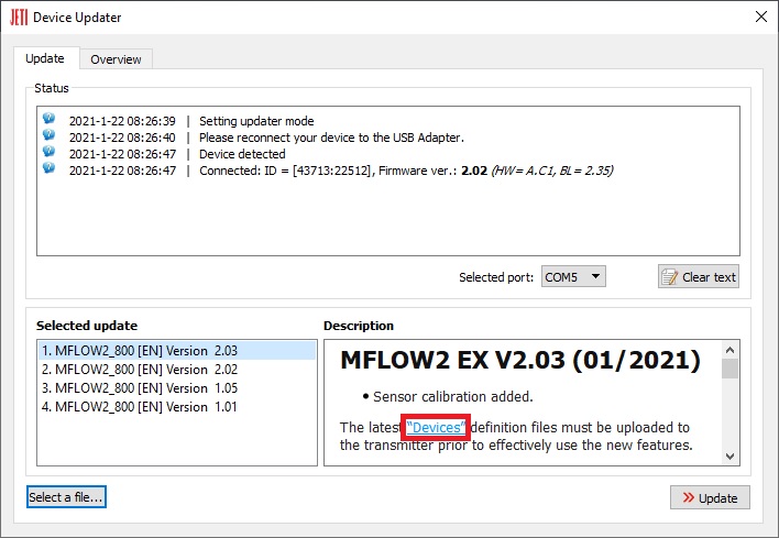
Calibration of the consumed volume is possible from FW version 2.03.We recommend that you first check SW version in the MFlow2 EX sensor. If will be necessary, update the sensor via the JETI Studio program.
It is also necessary to have the actual device profile (MFlow2.bin) in the "Devices" folder on the transmitter's SD card. Actual device profile can be downloaded during the MFlow2 EX sensor update, or you can update your transmitter via the JETI Studio program. The file (MFlow2.bin) will be automatically updated on the transmitter's SD card.
Calibration procedure (as example): Leave the "calibration" in the default setting (1,000) and make the first test flight (or run a pumping test with the correct type of fuel). In our example the sensor in the default setting measured the consumed volume of fuel 1159 ml. After a test flight (or pumping test) we measure the exact volume of fuel consumed from the tank, for example, by pouring the rest of the fuel from the tank into the calibration cylinder. In this way, we can exactly determine “real consumed volume” from tank. Then in the calibration menu fill in this exact volume in the item "real consumed volume" (980 ml). The flow coefficient is automatically set to the exact value (0.845). You can reset the calibration at any time and select another (more accurate) value to suit.